Live – Motor & VFD Principles Course
Learn the general function of motors and VFDs, application considerations, and factors to consider in their installation, operation and maintenance.
Motor Frame Size and Dimension Reference Tool
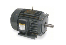
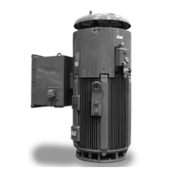
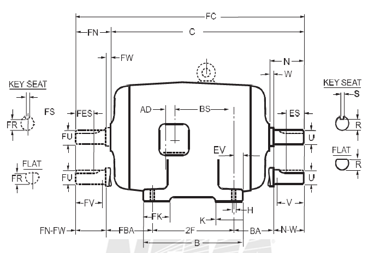
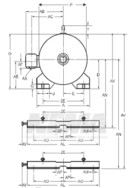
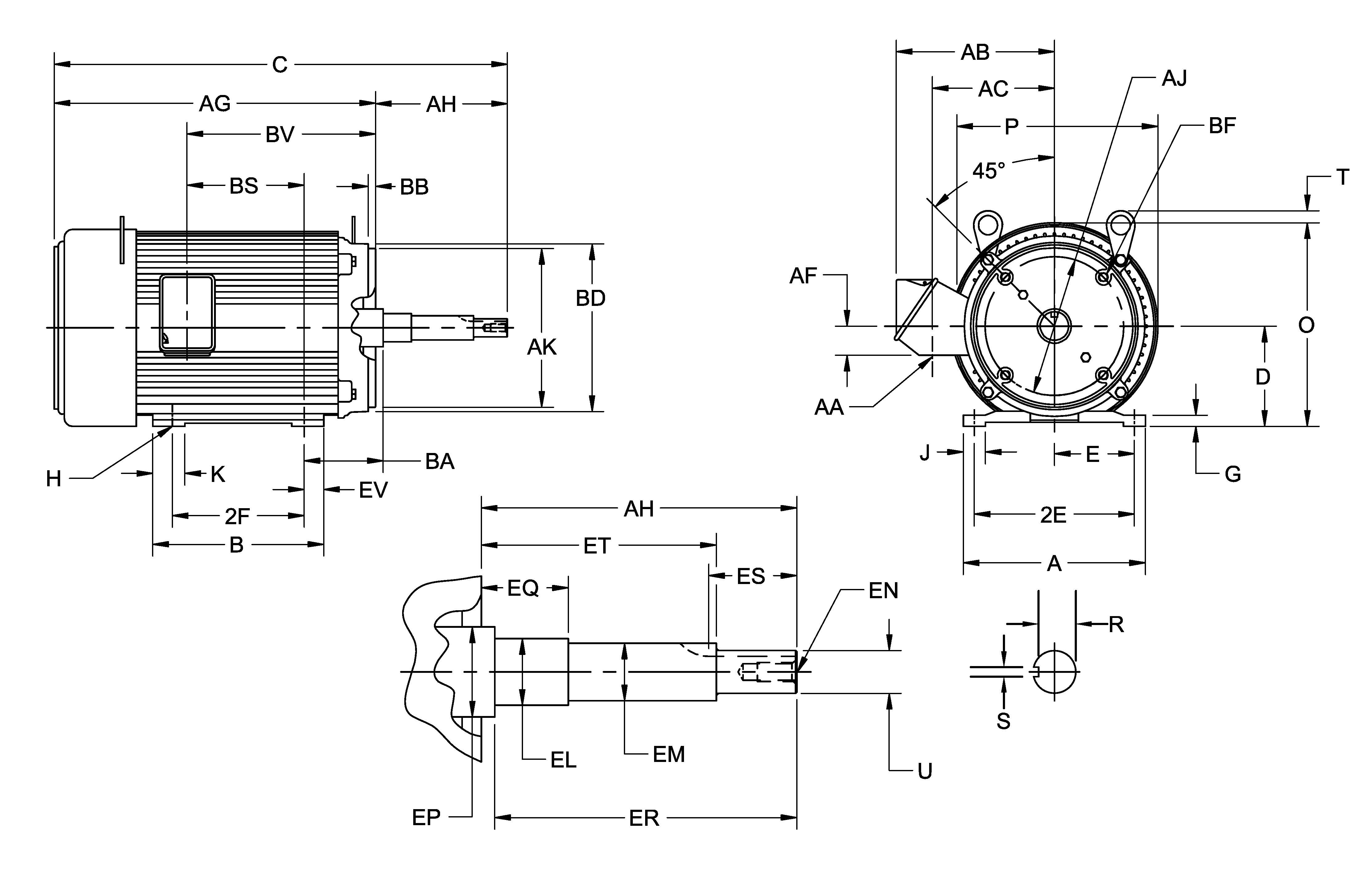
Horizontal Electric Motor
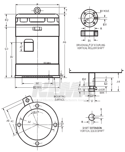
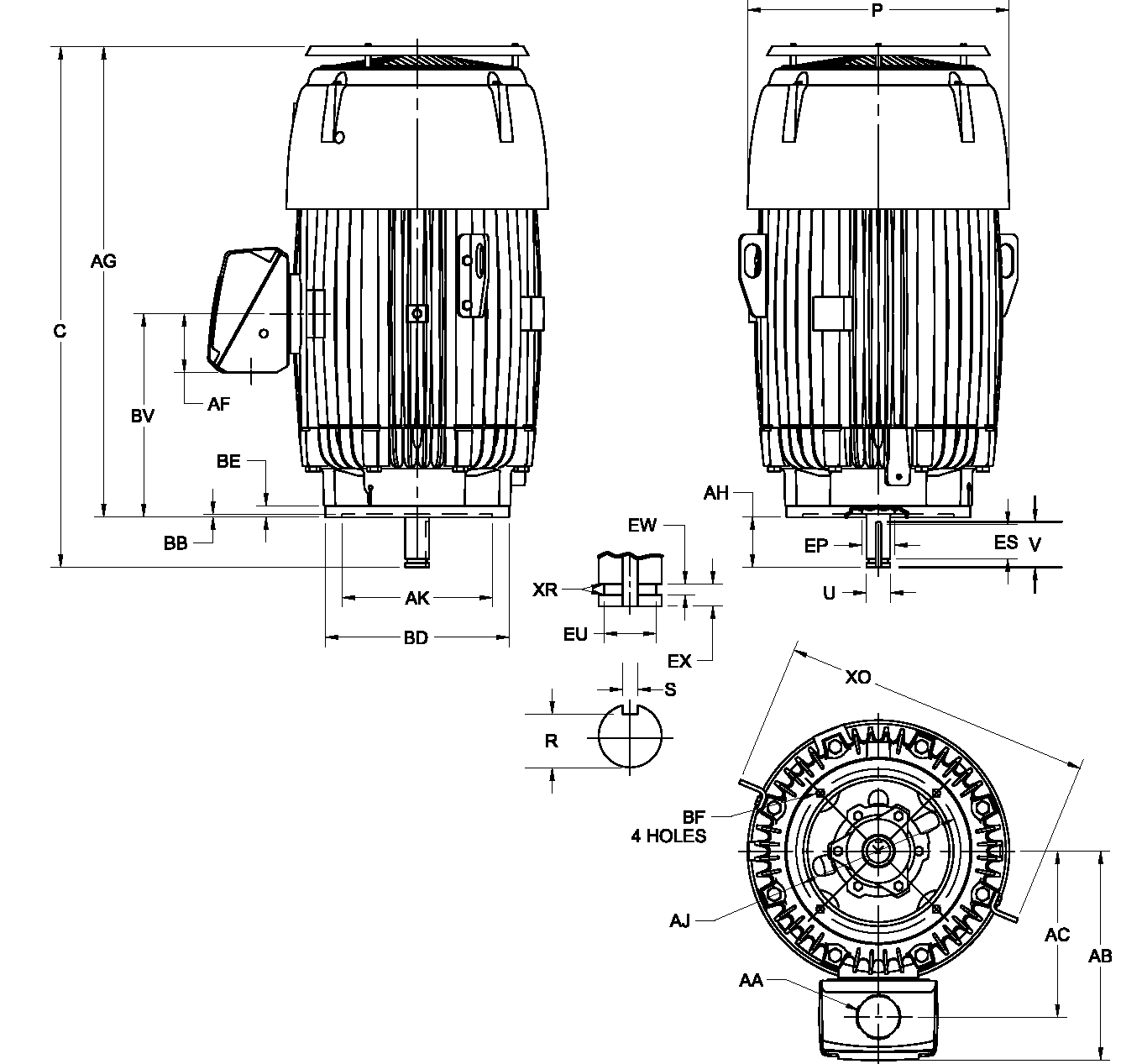
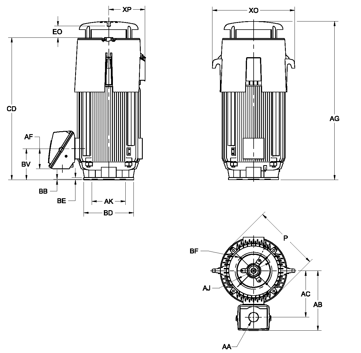
Vertical Electric Motor

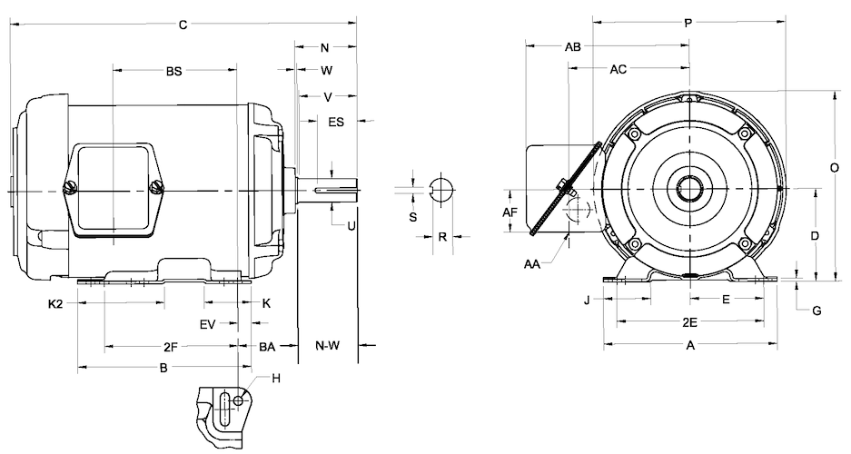
Drawings represent standard TEFC general purpose motors and are for example or reference only
†Frames 42 to 56H, inclusive—The tolerance for the 2F dimension shall be ±0.03 inch and for the H dimension (width of slot) shall be +0.02 inch, −0.00 inch.
Frames 143T to 500, inclusive—The tolerance for the 2E and 2F dimensions shall be ±0.03 inch and for the H dimension shall be +0.05 inch, −0.00 inch.
The values of the H dimension represent standard bolt sizes plus dimensional clearances.
H dimension:
Frames 143T to 365T, inclusive—The clearance of the std. bolt to hole size is 0.03 inch. The tolerance is +0.05, −0.00 inch.
Frames 404T to 449T, inclusive—The clearance of the std. bolt to hole size is 0.06 inch. The tolerance is +0.020 inch, −0.00 inch.
††For dimensions of clearance holes, see 4.8.
**For the 2F dimension and corresponding third (and when required, the fourth) digit in the frame series, see 4.2.1 and Table 4-2.
***BA tolerance: ±0.09 inch.
| Frame Designation | A Max | D* | E† | 2F† | BA*** | H† | U | N-W | V Min | R | ES Min | S | AA Min†† |
|---|---|---|---|---|---|---|---|---|---|---|---|---|---|
| 42 | — | 2.62 | 1.75 | 1.69 | 2.06 | 0.28 slot | 0.375 | 1.12 | — | 0.328 | — | flat | — |
| 48 | — | 3 | 2.12 | 2.75 | 2.5 | 0.34 slot | 0.5 | 1.5 | — | 0.453 | — | flat | — |
| 48H | — | 3 | 2.12 | 4.75 | 2.5 | 0.34 slot | 0.5 | 1.5 | — | 0.453 | — | flat | — |
| 56 | — | 3.5 | 2.44 | 3 | 2.75 | 0.34 slot | 0.625 | 1.88 | — | 0.517 | 1.41 | 0.188 | — |
| 56H | — | 3.5 | 2.44 | 5 | 2.75 | 0.34 slot | 0.625 | 1.88 | — | 0.517 | 1.41 | 0.188 | — |
| 143T | 7 | 3.5 | 2.75 | 4 | 2.25 | 0.34 hole | 0.875 | 2.25 | 2 | 0.771 | 1.41 | 0.188 | 3/4 |
| 145T | 7 | 3.5 | 2.75 | 5 | 2.25 | 0.34 hole | 0.875 | 2.25 | 2 | 0.771 | 1.41 | 0.188 | 3/4 |
| 182T | 9 | 4.5 | 3.75 | 4.5 | 2.75 | 0.41 hole | 1.125 | 2.75 | 2.5 | 0.986 | 1.78 | 0.25 | 3/4 |
| 184T | 9 | 4.5 | 3.75 | 5.5 | 2.75 | 0.41 hole | 1.125 | 2.75 | 2.5 | 0.986 | 1.78 | 0.25 | 3/4 |
| 213T | 10.5 | 5.25 | 4.25 | 5.5 | 3.5 | 0.41 hole | 1.375 | 3.38 | 3.12 | 1.201 | 2.41 | 0.312 | 1 |
| 215T | 10.5 | 5.25 | 4.25 | 7 | 3.5 | 0.41 hole | 1.375 | 3.38 | 3.12 | 1.201 | 2.41 | 0.312 | 1 |
| 254T | 12.5 | 6.25 | 5 | 8.25 | 4.25 | 0.53 hole | 1.625 | 4 | 3.75 | 1.416 | 2.91 | 0.375 | 1-1/4 |
| 256T | 12.5 | 6.25 | 5 | 10 | 4.25 | 0.53 hole | 1.625 | 4 | 3.75 | 1.416 | 2.91 | 0.375 | 1-1/4 |
| 284T | 14 | 7 | 5.5 | 9.5 | 4.75 | 0.53 hole | 1.875 | 4.62 | 4.38 | 1.591 | 3.28 | 0.5 | 1-1/2 |
| 284TS | 14 | 7 | 5.5 | 9.5 | 4.75 | 0.53 hole | 1.625 | 3.25 | 3 | 1.416 | 1.91 | 0.375 | 1-1/2 |
| 286T | 14 | 7 | 5.5 | 11 | 4.75 | 0.53 hole | 1.875 | 4.62 | 4.38 | 1.591 | 3.28 | 0.5 | 1-1/2 |
| 286TS | 14 | 7 | 5.5 | 11 | 4.75 | 0.53 hole | 1.625 | 3.25 | 3 | 1.416 | 1.91 | 0.375 | 1-1/2 |
| 324T | 16 | 8 | 6.25 | 10.5 | 5.25 | 0.66 hole | 2.125 | 5.25 | 5 | 1.845 | 3.91 | 0.5 | 2 |
| 324TS | 16 | 8 | 6.25 | 10.5 | 5.25 | 0.66 hole | 1.875 | 3.75 | 3.5 | 1.591 | 2.03 | 0.5 | 2 |
| 326T | 16 | 8 | 6.25 | 12 | 5.25 | 0.66 hole | 2.125 | 5.25 | 5 | 1.845 | 3.91 | 0.5 | 2 |
| 326TS | 16 | 8 | 6.25 | 12 | 5.25 | 0.66 hole | 1.875 | 3.75 | 3.5 | 1.591 | 2.03 | 0.5 | 2 |
| 364T | 18 | 9 | 7 | 11.25 | 5.88 | 0.66 hole | 2.375 | 5.88 | 5.62 | 2.021 | 4.28 | 0.625 | 3 |
| 364TS | 18 | 9 | 7 | 11.25 | 5.88 | 0.66 hole | 1.875 | 3.75 | 3.5 | 1.591 | 2.03 | 0.5 | 3 |
| 365T | 18 | 9 | 7 | 12.25 | 5.88 | 0.66 hole | 2.375 | 5.88 | 5.62 | 2.021 | 4.28 | 0.625 | 3 |
| 365TS | 18 | 9 | 7 | 12.25 | 5.88 | 0.66 hole | 1.875 | 3.75 | 3.5 | 1.591 | 2.03 | 0.5 | 3 |
| 404T | 20 | 10 | 8 | 12.25 | 6.62 | 0.81 hole | 2.875 | 7.25 | 7 | 2.45 | 5.65 | 0.75 | 3 |
| 404TS | 20 | 10 | 8 | 12.25 | 6.62 | 0.81 hole | 2.125 | 4.25 | 4 | 1.845 | 2.78 | 0.5 | 3 |
| 405T | 20 | 10 | 8 | 13.75 | 6.62 | 0.81 hole | 2.875 | 7.25 | 7 | 2.45 | 5.65 | 0.75 | 3 |
| 405TS | 20 | 10 | 8 | 13.75 | 6.62 | 0.81 hole | 2.125 | 4.25 | 4 | 1.845 | 2.78 | 0.5 | 3 |
| 444T | 22 | 11 | 9 | 14.5 | 7.5 | 0.81 hole | 3.375 | 8.5 | 8.25 | 2.88 | 6.91 | 0.875 | 3 |
| 444TS | 22 | 11 | 9 | 14.5 | 7.5 | 0.81 hole | 2.375 | 4.75 | 4.5 | 2.021 | 3.03 | 0.625 | 3 |
| 445T | 22 | 11 | 9 | 16.5 | 7.5 | 0.81 hole | 3.375 | 8.5 | 8.25 | 2.88 | 6.91 | 0.875 | 3 |
| 445TS | 22 | 11 | 9 | 16.5 | 7.5 | 0.81 hole | 2.375 | 4.75 | 4.5 | 2.021 | 3.03 | 0.625 | 3 |
| 447T | 22 | 11 | 9 | 20 | 7.5 | 0.81 hole | 3.375 | 8.5 | 8.25 | 2.88 | 6.91 | 0.875 | 3 |
| 447TS | 22 | 11 | 9 | 20 | 7.5 | 0.81 hole | 2.375 | 4.75 | 4.5 | 2.021 | 3.03 | 0.625 | 3 |
| 449T | 22 | 11 | 9 | 25 | 7.5 | 0.81 hole | 3.375 | 8.5 | 8.25 | 2.88 | 6.91 | 0.875 | 3 |
| 449TS | 22 | 11 | 9 | 25 | 7.5 | 0.81 hole | 2.375 | 4.75 | 4.5 | 2.021 | 3.03 | 0.625 | 3 |
| 440 | — | 11 | 9 | ** | 7.5 | — | — | — | — | — | — | — | — |
| 500 | — | 12.5 | 10 | ** | 8.5 | — | — | — | — | — | — | — | — |
Tbl. 5.I.1
*The tolerances on the D dimension for rigid base motors shall be +0.00 inch, −0.06 inch. No tolerance has been established for the D dimension of resilient mounted motors.†Frames 42 to 56H, inclusive—The tolerance for the 2F dimension shall be ±0.03 inch and for the H dimension (width of slot) shall be +0.02 inch, −0.00 inch.
Frames 143T to 500, inclusive—The tolerance for the 2E and 2F dimensions shall be ±0.03 inch and for the H dimension shall be +0.05 inch, −0.00 inch.
The values of the H dimension represent standard bolt sizes plus dimensional clearances.
H dimension:
Frames 143T to 365T, inclusive—The clearance of the std. bolt to hole size is 0.03 inch. The tolerance is +0.05, −0.00 inch.
Frames 404T to 449T, inclusive—The clearance of the std. bolt to hole size is 0.06 inch. The tolerance is +0.020 inch, −0.00 inch.
††For dimensions of clearance holes, see 4.8.
**For the 2F dimension and corresponding third (and when required, the fourth) digit in the frame series, see 4.2.1 and Table 4-2.
***BA tolerance: ±0.09 inch.
Notes:
- For the meaning of the letter dimensions, see 4.1 and Figures 4-1 and 4-2.
- For tolerances on shaft extension diameters and keyseats, see 4.9.
- Frames 42 to 56H, inclusive—if the shaft extension length of the motor is not suitable for the application, it is recommended that deviations from this length be in 0.25 inch increments.
- For cast-iron products, bottom of feet coplanar: 0.015 inch.
- For cast-iron products, foot top parallel to foot bottom: 1.5 degree.
- For cast-iron products, shaft parallel to foot plan: 0.015 inch.
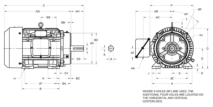
Drawings represent standard TEFC general purpose motors and are for example or reference only
*For frames 42C to 445TSC, see 4.4.1, for dimensions A, D, E, 2F, and H.
**For frames 182TC, 184TC, and 213TC through 500TC, the centerline of the bolt holes shall be within 0.025 inch of true location. True location is defined as angular and diametrical location with reference to the centerline of the AK dimension.
†The tolerance on this BB dimension shall be +0.00 inch, −0.06 inch.
††These BD dimensions are nominal dimensions.
†††For dimensions of clearance holes, see 4.8.
| Frame Designation* | AJ** | AK | BA | BB Min | BC | BD Max | BF Hole Number | BF Hole Tap Size | BF Hole Bolt Penetration Allowance | U | AH | Keyseat - R | Keyseat - ES Min | Keyseat - S | AA Min††† |
|---|---|---|---|---|---|---|---|---|---|---|---|---|---|---|---|
| 42C | 3.75 | 3 | 2.062 | 0.16† | -0.19 | 5.00†† | 4 | 1/4-20 | — | 0.375 | 1.312 | 0.328 | — | Flat | — |
| 48C | 3.75 | 3 | 2.5 | 0.16† | -0.19 | 5.625 | 4 | 1/4-20 | — | 0.5 | 1.69 | 0.453 | — | flat | — |
| 56C | 5.875 | 4.5 | 2.75 | 0.16† | -0.19 | 6.50†† | 4 | 3/8-16 | — | 0.625 | 2.06 | 0.517 | 1.41 | 0.188 | — |
| 143TC and 145TC | 5.875 | 4.5 | 2.75 | 0.16† | 0.12 | 6.50†† | 4 | 3/8-16 | 0.56 | 0.875 | 2.12 | 0.771 | 1.41 | 0.188 | 3/4 |
| 182TC and 184TC | 7.25 | 8.5 | 3.5 | 0.25 | 0.12 | 9 | 4 | 1/2-13 | 0.75 | 1.125 | 2.62 | 0.986 | 1.78 | 0.25 | 3/4 |
| 182TCH and 184TCH | 5.875 | 4.5 | 3.5 | 0.16† | 0.12 | 6.50†† | 4 | 3/8-16 | 0.56 | 1.125 | 2.62 | 0.986 | 1.78 | 0.25 | 3/4 |
| 213TC and 215TC | 7.25 | 8.5 | 4.25 | 0.25 | 0.25 | 9 | 4 | 1/2-13 | 0.75 | 1.375 | 3.12 | 1.201 | 2.41 | 0.312 | 1 |
| 254TC and 256TC | 7.25 | 8.5 | 4.75 | 0.25 | 0.25 | 10 | 4 | 1/2-13 | 0.75 | 1.625 | 3.75 | 1.416 | 2.91 | 0.375 | 1-1/4 |
| 284TC and 286TC | 9 | 10.5 | 4.75 | 0.25 | 0.25 | 11.25 | 4 | 1/2-13 | 0.75 | 1.875 | 4.38 | 1.591 | 3.28 | 0.5 | 1-1/2 |
| 284TSC and 286TSC | 9 | 10.5 | 4.75 | 0.25 | 0.25 | 11.25 | 4 | 1/2-13 | 0.75 | 1.625 | 3 | 1.416 | 1.91 | 0.375 | 1-1/2 |
| 324TC and 326TC | 11 | 12.5 | 5.25 | 0.25 | 0.25 | 14 | 4 | 5/8-11 | 0.94 | 2.125 | 5 | 1.845 | 3.91 | 0.5 | 2 |
| 324TSC and 326TSC | 11 | 12.5 | 5.25 | 0.25 | 0.25 | 14 | 4 | 5/8-11 | 0.94 | 1.875 | 3.5 | 1.591 | 2.03 | 0.5 | 2 |
| 364TC and 365TC | 11 | 12.5 | 5.88 | 0.25 | 0.25 | 14 | 8 | 5/8-11 | 0.94 | 2.375 | 5.62 | 2.021 | 4.28 | 0.625 | 3 |
| 364TSC and 365TSC | 11 | 12.5 | 5.88 | 0.25 | 0.25 | 14 | 8 | 5/8-11 | 0.94 | 1.875 | 3.5 | 1.591 | 2.03 | 0.5 | 3 |
| 404TC and 405TC | 11 | 12.5 | 6.62 | 0.25 | 0.25 | 15.5 | 8 | 5/8-11 | 0.94 | 2.875 | 7 | 2.45 | 5.65 | 0.75 | 3 |
| 404TSC and 405TSC | 11 | 12.5 | 6.62 | 0.25 | 0.25 | 15.5 | 8 | 5/8-11 | 0.94 | 2.125 | 4 | 1.845 | 2.78 | 0.5 | 3 |
| 444TC and 445TC | 14 | 16 | 7.5 | 0.25 | 0.25 | 18 | 8 | 5/8-11 | 0.94 | 3.375 | 8.25 | 2.88 | 6.91 | 0.875 | 3 |
| 444TSC and 445TSC | 14 | 16 | 7.5 | 0.25 | 0.25 | 18 | 8 | 5/8-11 | 0.94 | 2.375 | 4.5 | 2.021 | 3.03 | 0.625 | 3 |
| 447TC and 449TC | 14 | 16 | 7.5 | 0.25 | 0.25 | 18 | 8 | 5/8-11 | 0.94 | 3.375 | 8.25 | 2.88 | 6.91 | 0.875 | 3 |
| 447TSC and 449TSC | 14 | 16 | 7.5 | 0.25 | 0.25 | 18 | 8 | 5/8-11 | 0.94 | 2.375 | 4.5 | 2.021 | 3.03 | 0.625 | 3 |
| 500 frame series | 14.5 | 16.5 | — | 0.25 | 0.25 | 18 | 4 | 5/8-11 | 0.94 | — | — | — | — | — | — |
Tbl. 5.I.2
All dimensions in inches.*For frames 42C to 445TSC, see 4.4.1, for dimensions A, D, E, 2F, and H.
**For frames 182TC, 184TC, and 213TC through 500TC, the centerline of the bolt holes shall be within 0.025 inch of true location. True location is defined as angular and diametrical location with reference to the centerline of the AK dimension.
†The tolerance on this BB dimension shall be +0.00 inch, −0.06 inch.
††These BD dimensions are nominal dimensions.
†††For dimensions of clearance holes, see 4.8.
Notes:
- For the meaning of the letter dimensions, see 4.1 and Figure 4-3.
- For tolerances on shaft extension diameters and keyseats, see 4.9.
- For tolerances on AK dimensions, face runout, and permissible eccentricity of mounting rabbet, see 4.12.
- If the shaft extension length of the motor is not suitable for the application, it is recommended that deviations from this length be in 0.25 inch increments.
| Frame Designations | FAJ | FAK | FBB Min | FBD Min | FBF Hole Number | FBF Hole Tap Size | FBF Hole Bolt Penetration Allowance | Hole for Accessory Leads†† DP | Hole for Accessory Leads†† Diameter |
|---|---|---|---|---|---|---|---|---|---|
| 143TFC and 145TFC | 5.875 | 4.5 | 0.16* | 6.50† | 4 | 3/8-16 | 0.56 | 2.81 | 0.41 |
| 182TFC and 184TFC | 5.875 | 4.5 | 0.16* | 6.50† | 4 | 3/8-16 | 0.56 | 2.81 | 0.41 |
| 213TFC and 215TFC | 7.25 | 8.5 | 0.25 | 9 | 4 | 1/2-13 | 0.75 | 3.81 | 0.62 |
| 254TFC and 256TFC | 7.25 | 8.5 | 0.25 | 10 | 4 | 1/2-13 | 0.75 | 3.81 | 0.62 |
| 284TFC and 286TFC | 9 | 10.5 | 0.25 | 11.25 | 4 | 1/2-13 | 0.75 | 4.5 | 0.62 |
| 324TFC and 326TFC | 11 | 12.5 | 0.25 | 14 | 4 | 5/8-11 | 0.94 | 5.25 | 0.62 |
Tbl. 5.I.3
*The tolerance on this FBB dimension shall be +0.00, −0.06 inch.†This BD dimension is a nominal dimension.
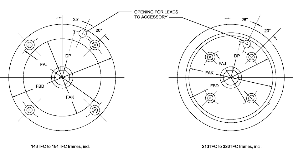
††When a hole is required in the Type C face for accessory leads, the hole shall be located relative to one of the FBF holes in accordance with the following figure and the table.
| Frame Designations* | AJ** | AK | BB Min | BD Max | BF clearance hole number | BF Clearnace Hole Size | U | V Min | AH† | Keyseat - R | Keyseat - ES (Min) | Keyseat - S | EU |
|---|---|---|---|---|---|---|---|---|---|---|---|---|---|
| 143VP and 145VP | 9.125 | 8.25 | 0.19 | 10 | 4 | 0.44 | 0.875 | 2.75 | 2.75 | 0.771-0.756 | 1.28 | 0.190-0.188 | 0.6875 |
| 182VP and 184VP | 9.125 | 8.25 | 0.19 | 10 | 4 | 0.44 | 1.125 | 2.75 | 2.75 | 0.986-0.971 | 1.28 | 0.252-0.250 | 0.875 |
| 213VP and 215VP | 9.125 | 8.25 | 0.19 | 10 | 4 | 0.44 | 1.125 | 2.75 | 2.75 | 0.986-0.971 | 1.28 | 0.252-0.250 | 0.875 |
| 254VP and 256VP | 9.125 | 8.25 | 0.19 | 10 | 4 | 0.44 | 1.125 | 2.75 | 2.75 | 0.986-0.971 | 1.28 | 0.252-0.250 | 0.875 |
| 284VP and 286VP | 9.125 | 8.25 | 0.19 | 10 | 4 | 0.44 | 1.125 | 2.75 | 2.75 | 0.986-0.971 | 1.28 | 0.252-0.250 | 0.875 |
| 324VP and 326VP | 14.75 | 13.5 | 0.25 | 16.5 | 4 | 0.69 | 1.625 | 4.5 | 4.5 | 1.416-1.401 | 3.03 | 0.377-0.375 | 1.25 |
| 364VP and 365VP | 14.75 | 13.5 | 0.25 | 16.5 | 4 | 0.69 | 1.625 | 4.5 | 4.5 | 1.416-1.401 | 3.03 | 0.377-0.375 | 1.25 |
| 404VP and 405VP | 14.75 | 13.5 | 0.25 | 16.5 | 4 | 0.69 | 1.625 | 4.5 | 4.5 | 1.416-1.401 | 3.03 | 0.377-0.375 | 1.25 |
| 444VP and 445VP | 14.75 | 13.5 | 0.25 | 16.5 | 4 | 0.69 | 2.125 | 4.5 | 4.5 | 1.845-1.830 | 3.03 | 0.502-0.500 | 1.75 |
| 447VP and 449VP | 14.75 | 13.5 | 0.25 | 16.5 | 4 | 0.69 | 2.125 | 4.5 | 4.5 | 1.845-1.830 | 3.03 | 0.502-0.500 | 1.75 |
Tbl. 5.I.4
The tolerance for the permissible shaft runout shall be 0.002 inch indicator reading (see 4.11).For the meaning of the letter dimensions, see 4.1 and Figure 18-22.
For tolerance on AK dimension, face runout, and permissible eccentricity of mounting rabbet, see 4.12.
For tolerance on shaft extension diameters and keyseats, see 4.9 and 4.10.
*The assignment of horsepower and speed ratings to these frames shall be in accordance with Part 13, except for the inclusion of the suffix letter VP in place of the suffix letters T and TS.
**AJ dimension—centerline of bolt holes shall be within 0.025 inch of true location. True location is defined as angular and diametrical location with reference to the centerline of the AK dimension.
†The tolerance on the AH dimension shall be ±0.06 inch. Dimension AH shall be measured with motor in vertical position, shaft down.
| Item* | Frame Designation | AJ** | AK | BB Min | BD Max | Clearance | BF Tap Size | Number | EO Min |
|---|---|---|---|---|---|---|---|---|---|
| 1 | 182TP | 9.125 | 8.25 | 0.19 | 10 | 0.44 | — | 4 | 2.5 |
| 2 | 184TP | 9.125 | 8.25 | 0.19 | 10 | 0.44 | — | 4 | 2.5 |
| 3 | 213TP | 9.125 | 8.25 | 0.19 | 10 | 0.44 | — | 4 | 2.5 |
| 4 | 215TP | 9.125 | 8.25 | 0.19 | 10 | 0.44 | — | 4 | 2.5 |
| 5 | 254TP | 9.125 | 8.25 | 0.19 | 10 | 0.44 | — | 4 | 2.75 |
| 6 | 256TP | 9.125 | 8.25 | 0.19 | 10 | 0.44 | — | 4 | 2.75 |
| 7 | 284TP† | 9.125 | 8.25 | 0.19 | 10 | 0.44 | — | 4 | 2.75 |
| 8 | 286TP† | 9.125 | 8.25 | 0.19 | 10 | 0.44 | — | 4 | 2.75 |
| 9 | 324TP† | 14.75 | 13.5 | 0.25 | 16.5 | 0.69 | — | 4 | 4 |
| 10 | 326TP† | 14.75 | 13.5 | 0.25 | 16.5 | 0.69 | — | 4 | 4 |
| 11 | 364TP† | 14.75 | 13.5 | 0.25 | 16.5 | 0.69 | — | 4 | 4 |
| 12 | 365TP | 14.75 | 13.5 | 0.25 | 16.5 | 0.69 | — | 4 | 4 |
| 13 | 404TP | 14.75 | 13.5 | 0.25 | 16.5 | 0.69 | — | 4 | 4.5 |
| 14 | 405TP | 14.75 | 13.5 | 0.25 | 16.5 | 0.69 | — | 4 | 4.5 |
| 15 | 444TP | 14.75 | 13.5 | 0.25 | 16.5 | 0.69 | — | 4 | 5 |
| 16 | 445TP | 14.75 | 13.5 | 0.25 | 16.5 | 0.69 | — | 4 | 5 |
| 17 | — | 14.75 | 13.5 | 0.25 | 0.69 | — | 4 | — | |
| 18 | — | 14.75 | 13.5 | 0.25 | 0.69†† | 5/8-11 | 4 | — | |
| 19 | — | 26 | 22 | 0.25 | 0.81†† | 3/4-10 | 4 | — | |
| 324TPH | 9.125 | 8.25 | 0.19 | 12 | 0.44 | — | 4 | 4 | |
| 326TPH | 9.125 | 8.25 | 0.19 | 12 | 0.44 | — | 4 | 4 | |
| 284TPH | 14.75 | 13.5 | 0.25 | 16.5 | 0.69 | — | 4 | 2.75 | |
| 286TPH | 14.75 | 13.5 | 0.25 | 16.5 | 0.69 | — | 4 | 2.75 |
Tbl. 5.I.5
All dimensions in inches.*See Table 18-31 for the coupling dimensions of the motors covered in items 1 through 16.
†These frames have the following alternative base dimensions, the coupling dimensions given in Table 18-31 remaining unchanged.
††Either clearance hole or up size shall be specified.
**AJ dimension—centerline of bolt holes shall be within 0.025 inch of true location. True location is defined as angular and diametrical location with reference to the centerline of the AK dimension.
| Frame Designations | U | AH* | AJ** | AK | BB | BD Max | BF Number | BF Tap Size | BF Bolt Penetration Allowance | EL |
|---|---|---|---|---|---|---|---|---|---|---|
| 143JM and 145JM | 0.8745 - 0.8740 | 4.281 - 4.219 | 5.875 | 4.500 - 4.497 | 0.156 - 0.125 | 6.62 | 4 | 3/8-16 | 0.56 | 1.156 - 1.154 |
| 143JP and 145JP | 0.8745 - 0.8740 | 7.343 - 7.281 | 5.875 | 4.500 - 4.497 | 0.156 - 0.125 | 6.62 | 4 | 3/8-16 | 0.56 | 1.156 - 1.154 |
| 182JM and 184JM | 0.8745 - 0.8740 | 4.281 - 4.219 | 5.875 | 4.500 - 4.497 | 0.156 - 0.125 | 6.62 | 4 | 3/8-16 | 0.56 | 1.250 - 1.248 |
| 182JP and 184JP | 0.8745 - 0.8740 | 7.343 - 7.281 | 5.875 | 4.500 - 4.497 | 0.156 - 0.125 | 6.62 | 4 | 3/8-16 | 0.56 | 1.250 - 1.248 |
| 213JM and 215JM | 0.8745 - 0.8740 | 4.281 - 4.219 | 7.25 | 8.500 - 8.497 | 0.312 - 0.250 | 9 | 4 | 1/2-13 | 0.75 | 1.250 - 1.248 |
| 213JP and 215JP | 1.2495 - 1.2490 | 8.156 - 8.094 | 7.25 | 8.500 - 8.497 | 0.312 - 0.250 | 9 | 4 | 1/2-13 | 0.75 | 1.750 - 1.748 |
| 254JM and 256JM | 1.2495 - 1.2490 | 5.281 - 5.219 | 7.25 | 8.500 - 8.497 | 0.312 - 0.250 | 10 | 4 | 1/2-13 | 0.75 | 1.750 - 1.748 |
| 254JP and 256JP | 1.2495 - 1.2490 | 8.156 - 8.094 | 7.25 | 8.500 - 8.497 | 0.312 - 0.250 | 10 | 4 | 1/2-13 | 0.75 | 1.750 - 1.748 |
| 284JM and 286JM | 1.2495 - 1.2490 | 5.281 - 5.219 | 11 | 12.500 - 12.495 | 0.312 - 0.250 | 14 | 4 | 5/8-11 | 0.94 | 1.750 - 1.748 |
| 284JP and 286JP | 1.2495 - 1.2490 | 8.156 - 8.094 | 11 | 12.500 - 12.495 | 0.312 - 0.250 | 14 | 4 | 5/8-11 | 0.94 | 1.750 - 1.748 |
| 324JM and 326JM | 1.2495 - 1.2490 | 5.281 - 5.219 | 11 | 12.500 - 12.495 | 0.312 - 0.250 | 14 | 4 | 5/8-11 | 0.94 | 1.750 - 1.748 |
| 324JP and 326JP | 1.2495 - 1.2490 | 8.156 - 8.094 | 11 | 12.500 - 12.495 | 0.312 - 0.250 | 14 | 4 | 5/8-11 | 0.94 | 1.750 - 1.748 |
| 364JP and 365JP | 1.6245 - 1.6240 | 8.156 - 8.094 | 11 | 12.500 - 12.495 | 0.312 - 0.250 | 14 | 4 | 5/8-11 | 0.94 | 2.125 - 2.123 |
Tbl. 5.I.6
| Frame Designations | EM | EN Tap size | EN Tap Drill Penetration Allowance | EN - Bolt Penetration Allowance | EP Min | EQ* | ER Min | Keyseat - R | Keyseat - ES (Min) | Keyseat - S | ET* |
|---|---|---|---|---|---|---|---|---|---|---|---|
| 143JM and 145JM | 1.0000 - 0.9995 | 3/8-16 | 1.12 | 0.75 | 1.156 | 0.640 - 0.610 | 4.25 | 0.771-0.756 | 1.65 | 0.190-0.188 | 2.890 - 2.860 |
| 143JP and 145JP | 1.0000 - 0.9995 | 3/8-16 | 1.12 | 0.75 | 1.156 | 1.578 - 1.548 | 7.312 | 0.771-0.756 | 1.65 | 0.190-0.188 | 5.952 - 5.922 |
| 182JM and 184JM | 1.0000 - 0.9995 | 3/8-16 | 1.12 | 0.75 | 1.25 | 0.640 - 0.610 | 4.25 | 0.771-0.756 | 1.65 | 0.190-0.188 | 2.890 - 2.860 |
| 182JP and 184JP | 1.0000 - 0.9995 | 3/8-16 | 1.12 | 0.75 | 1.25 | 1.578 - 1.548 | 7.312 | 0.771-0.756 | 1.65 | 0.190-0.188 | 5.952 - 5.922 |
| 213JM and 215JM | 1.0000 - 0.9995 | 3/8-16 | 1.12 | 0.75 | 1.75 | 0.640 - 0.610 | 4.25 | 0.771-0.756 | 1.65 | 0.190-0.188 | 2.890 - 2.860 |
| 213JP and 215JP | 1.3750 -1.3745 | 1/2-13 | 1.12 | 0.75 | 1.75 | 2.390 - 2.360 | 8.125 | 1.112 - 1.097 | 2.53 | 0.252-0.250 | 5.890 - 5.860 |
| 254JM and 256JM | 1.3750 - 1.3745 | 1/2-13 | 1.5 | 1 | 1.75 | 0.640 - 0.610 | 5.25 | 1.112 - 1.097 | 2.53 | 0.252-0.250 | 3.015 - 2.980 |
| 254JP and 256JP | 1.3750 -1.3745 | 1/2-13 | 1.5 | 1 | 1.75 | 2.390 - 2.360 | 8.125 | 1.112 - 1.097 | 2.53 | 0.252-0.250 | 5.890 - 5.860 |
| 284JM and 286JM | 1.3750 - 1.3745 | 1/2-13 | 1.5 | 1 | 2.125 | 0.645 - 0.605 | 5.25 | 1.112 - 1.097 | 2.53 | 0.252-0.250 | 3.015 - 2.980 |
| 284JP and 286JP | 1.3750 -1.3745 | 1/2-13 | 1.5 | 1 | 2.125 | 2.390 - 2.360 | 8.125 | 1.112 - 1.097 | 2.53 | 0.252-0.250 | 5.895 - 5.855 |
| 324JM and 326JM | 1.3750 - 1.3745 | 1/2-13 | 1.5 | 1 | 2.125 | 0.645 - 0.605 | 5.25 | 1.112 - 1.097 | 2.53 | 0.252-0.250 | 3.015 - 2.980 |
| 324JP and 326JP | 1.3750 -1.3745 | 1/2-13 | 1.5 | 1 | 2.125 | 2.395 - 2.355 | 8.125 | 1.112 - 1.097 | 2.53 | 0.252-0.250 | 5.895 - 5.855 |
| 364JP and 365JP | 1.7500 - 1.7495 | 1/2-13 | 1.5 | 1 | 2.5 | 2.395 - 2.355 | 8.125 | 1.416 - 1.401 | 2.53 | 0.377 - 0.375 | 5.895 - 5.855 |
Tbl. 5.I.7
All dimensions in inches.For the meaning of the letter dimensions, see Figures
*AH, EQ, and ET dimensions measured with the shaft pulled by hand away from the motor to the limit of endplay.
**AJ dimension—centerline of bolt holes is within 0.015 inch of true location for frames 154 to 256 JM and JP, inclusive, and within 0.025 inch of true location for frames 284 to 365 JM and JP, inclusive. True location is determined as angular and diametrical location with reference to the centerline of the AK dimension.
Face runout—
143JM/JP to 256JM/JP frames, inclusive, 0.004 inch indicator reading
284JM/JP to 326JM/JP frames, inclusive, 0.006 inch indicator reading
Permissible eccentricity of mounting rabbet—
143JM/JP to 256JM/JP frames, inclusive, 0.004 inch indicator reading
284JM/JP to 326JM/JP frames, inclusive, 0.006 inch indicator reading
Permissible shaft runout—
143JM/JP to 256JM/JP frames, inclusive, 0.002 inch indicator reading
284JM/JP to 326JM/JP frames, inclusive, 0.003 inch indicator reading
Last updated on July 19th, 2024

